
Treadmill Motor Controller - fl3xbl0w
Reverse engineering project. It started with the Bowflex Treadmill 22 but ended up being generalized for any Android-powered machine sold by Nautilus Inc. (Nautilus, Bowflex, Schwinn).
This mainly applies to the Treadmill 22 & Treadmill 56.
The motor control board is manufactured by Electronics Way Industry.

Given the service manual provided by Nautilus Inc. (backup on archive.org):

Focusing specifically on this part:

We can identify the “communication cable” that connects the motor controller as a 5-pin cable. There is only one 5-pin connector. I have labeled the cables with their corresponding colors (data & switch are opto-isolated):
| Cable Color | Label |
|---|---|
| red | GND |
| white | RXD |
| black | TXD |
| yellow | +12 |
| green | SW |
The board is not directly connected to the Android console.
The only 5-pin connector is from Molex. A Google search for “small Molex connectors” led me to an image of what they call Molex Micro-Fit 3.0 Single Row (5-Pin), which is used to connect the motor controller board:

By taking a look in NautilusLauncher.apk through jadx-gui, I can see that they communicate the Android tablet with their “Universal Console” using Serial at 230400 Baud (using /dev/ttyS4). THAT is NOT what we are analyzing here. That refers to the communication between Android and the “Universal Console”. We are investigating the communication between the “Button Panel Controller” and the “Motor Controller Board”, thus eliminating three boards as potential points of failure.
Trying to connect an ESP32 or a CH340-based Serial bridge directly to the cables between the treadmill base and the Bowflex controller board caused the treadmill base to not initialize correctly, after which I acquired a logic analyzer to investigate further.
Update 2025
In recent weeks, and almost three years after I started with this, several people have contacted me to ask about progress regarding this, confirming my initial assumption that the treadmill system is horrible and it was only a matter of time before machines started to fail. It seemed like a good time to put my logic analyzer to use, which until now had only been gathering dust.
Connecting the logic analyzer to the TXD and RXD lines (and GND, of course), I was immediately able to start intercepting messages between both parties without interrupting the communication. I suppose I initially couldn’t use an ESP32 due to impedance issues. After a few minutes of trial and error, I arrived at the following Serial configuration:
- 2400 Baud
- 8 Bits per Frame
- 1 Stop Bit
- No Parity Bit
- Least Significant Bit Sent First
- TXD: Inverted Signal
- RXD: Non Inverted Signal
With these settings, I could clearly see defined messages.
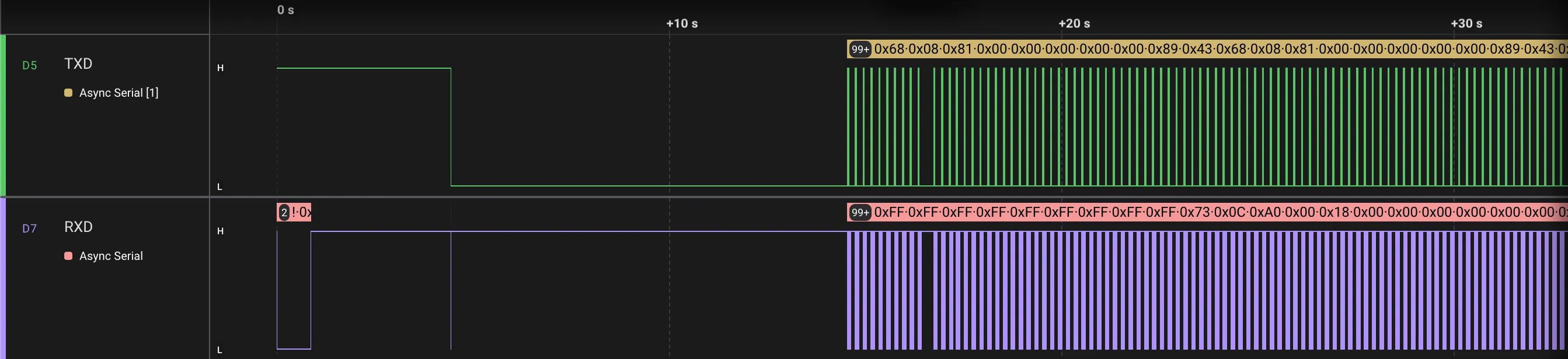
Intercepting UART messages during the booting process
Some things I noticed immediately:
- All messages sent by the button panel start with
0x68 - All messages sent by the motor controller board start with
0x73 - Messages from both parties end with
0x43 - Generally, messages from the button panel are sent 100ms after receiving a message from the motor controller board
- Except during the booting process, where in one instance there is a 300ms difference
- The noise on the communication lines is incredible, making message reading difficult
With that as a base, the process of deciphering the messages and understanding what is being communicated between both parties begins, making controlled changes in an exercise routine.
Intercepting Speed Changes
By making controlled changes to specific speeds, the following values sent to the motor controller board can be observed:
| Speed on Screen | Message Sent |
|---|---|
| 0.0 km/h (waiting or paused) | 0x68 0x08 0x80 0x50 0x00 0x0A 0x00 0x00 0xE2 0x43 |
| 2.0 km/h | 0x68 0x08 0x80 0x50 0x14 0x0A 0x00 0x00 0xF6 0x43 |
| 3.0 km/h | 0x68 0x08 0x80 0x50 0x1D 0x0A 0x00 0x00 0xFF 0x43 |
| 5.0 km/h | 0x68 0x08 0x80 0x50 0x31 0x0A 0x00 0x00 0x13 0x43 |
It can be observed that byte 5 and byte 9 change. Byte 5 appears to be the speed in hexadecimal, and byte 9 seems to be a checksum.
Converting the values of byte 5 to decimal:
| Speed on Screen | Hexadecimal | Decimal |
|---|---|---|
| 0.0 km/h (waiting or paused) | 0x00 | 0 |
| 2.0 km/h | 0x14 | 20 |
| 3.0 km/h | 0x1D | 29 |
| 5.0 km/h | 0x31 | 49 |
Having decompiled some parts of the Android system years ago, I remembered that when configuring the machine in the metric system, the Bowflex application internally performs the conversion from metric to imperial to communicate with the “UCB”. The motor controller board seems to use the metric system, and apparently, there is a loss of precision in the conversion from metric to imperial and then back to metric (which is what the motor controller expects), since everything is handled with 1 decimal of precision. Was it so difficult to do it right, Nautilus?
Considering that, and if a scaling factor of 10 is applied, it perfectly matches the values sent to the motor controller board. Therefore, the formula would be:
Decimal value = Speed in km/h × 10Intercepting Incline Changes
Following the same process as with speed, the following values sent to the motor controller board can be observed:
| Incline on Screen | Message Sent |
|---|---|
| -5° | 0x68 0x08 0x80 0x50 0x1D 0x00 0x00 0x00 0xF5 0x43 |
| 0° | 0x68 0x08 0x80 0x50 0x1D 0x32 0x00 0x00 0x27 0x43 |
| 9° | 0x68 0x08 0x80 0x50 0x1D 0x8C 0x00 0x00 0x81 0x43 |
In this case, byte 6 appears to be the incline in hexadecimal, and it confirms that byte 9 is a checksum.
Converting the values of byte 6 to decimal:
| Incline on Screen | Hexadecimal | Decimal |
|---|---|---|
| -5° | 0x00 | 0 |
| 0° | 0x32 | 50 |
| 9° | 0x8C | 140 |
The formula that perfectly matches the values sent to the motor controller board is:
Decimal value = (Angle + 5) × 10Checksum
This appears to be a simple and standard checksum in microcontrollers, adding all the bytes of the message and causing an overflow once it reaches 256. A simple representation would be something like:
uint8_t calculateChecksum(uint8_t *msg) {
  return msg[1] + msg[2] + msg[3] + msg[4] + msg[5] + msg[6] + msg[7];
}
By using uint8_t as the return type, the overflow occurs naturally. A for loop could be used to sum the values and return sum % 256, but it would be slower for microcontrollers without any real benefit.
Next Steps
- Gain a logical understanding of the booting process, or at least replicate it
- Capture interactions with the safety key (the red thing that is placed on clothing)
- Interpret the messages sent by the motor controller board, which should not differ much from the messages sent by the button panel
With that, the functionality of the button panel can be replicated, and with that, the treadmill can be controlled from a microcontroller.
— To Be Continued —